- 您现在的位置:买卖IC网 > Sheet目录1248 > TISP7400H3SL (Bourns Inc.)SURGE SUPP 300V BIDIR 3-SL
�� �
�
�TISP7xxxH3SL� Overvoltage� Protector� Series�
�APPLICATIONS� INFORMATION�
�Deployment�
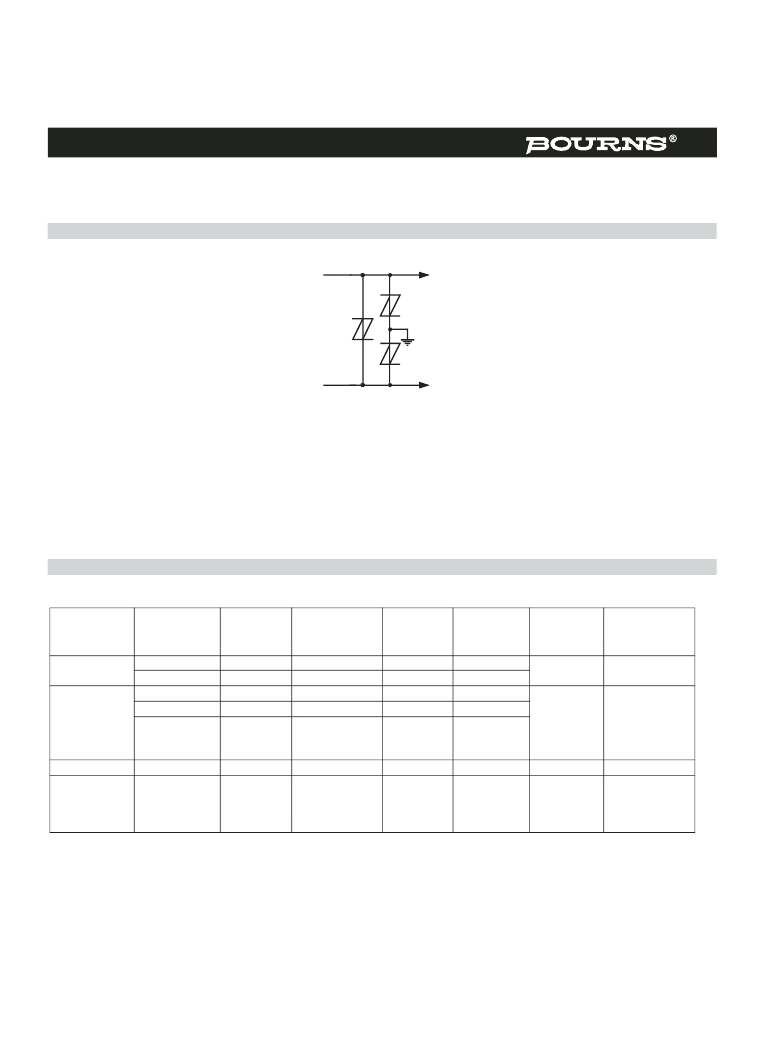
�These� devices� are� three� terminal� overvoltage� protectors.� They� limit� the� voltage� between� three� points� in� the� circuit.� Typically,� this� would� be� the�
�two� line� conductors� and� protective� ground� (Figure� 11).�
�Th3�
�Th1�
�Th2�
�Figure� 11.� MULTI-POINT� PROTECTION�
�In� Figure� 11,� protectors� Th2� and� Th3� limit� the� maximum� voltage� between� each� conductor� and� ground� to� the� ±� V(BO)� of� the� individual� protector.�
�Protector� Th1� limits� the� maximum� voltage� between� the� two� conductors� to� its� ±� V(BO)� value.�
�Manufacturers� are� being� increasingly� required� to� design� in� protection� coordination.� This� means� that� each� protector� is� operated� at� its� design�
�level� and� currents� are� diverted� through� the� appropriate� protector,� e.g.� the� primary� level� current� through� the� primary� protector� and� lower� levels�
�of� current� may� be� diverted� through� the� secondary� or� inherent� equipment� protection.� Without� coordination,� primary� level� currents� could� pass�
�through� the� equipment� only� designed� to� pass� secondary� level� currents.� To� ensure� coordination� happens� with� fixed� voltage� protectors,� some�
�resistance� is� normally� used� between� the� primary� and� secondary� protection.� The� values� given� in� this� data� sheet� apply� to� a� 400� V� (d.c.�
�sparkover)� gas� discharge� tube� primary� protector� and� the� appropriate� test� voltage� when� the� equipment� is� tested� with� a� primary� protector.�
�Impulse� Testing�
�To� verify� the� withstand� capability� and� safety� of� the� equipment,� standards� require� that� the� equipment� is� tested� with� various� impulse� wave� forms.�
�The� table� below� shows� some� common� values.�
�Peak� Voltage�
�Voltage�
�Peak� Current�
�Current�
�TISP7xxxH3�
�Series�
�Coordination�
�Standard�
�Setting�
�V�
�Waveform�
�μ� s�
�Value�
�A�
�Waveform�
�μ� s�
�25� °� C� Rating�
�A�
�Resistance�
�?�
�Resistance�
�(Min.)�
�GR-1089-CORE�
�2500� 2/10� 500� 2/10� 500�
�1000� 10/1000� 100� 10/1000� 100�
�0�
�NA�
�1500� 10/160� 200� 10/160� 250�
�FCC� Part� 68�
�(March� 1998)�
�800� 10/560� 100� 10/560� 130�
�1000� 9/720� ?� 25� 5/320� ?� 200�
�1500� (SINGLE)� 37.5� 5/320� ?� 200�
�0�
�NA�
�1500�
�(DUAL)�
�2� x� 27�
�4/250�
�2� x� 225�
�I� 31-24� 1500� 0.5/700� 37.5� 0.2/310� 200� 0�
�NA�
�1000�
�10/700�
�25�
�5/310�
�200�
�NA�
�ITU-T� K.20/K.21�
�1500�
�4000�
�4000�
�(SINGLE)�
�(SINGLE)�
�(DUAL)�
�37.5�
�100�
�2� x� 72�
�5/310�
�5/310�
�4/250�
�200�
�200�
�2� x� 225�
�0�
�NA�
�4.5�
�6.0�
�?� FCC� Part� 68� terminology� for� the� waveforms� produced� by� the� ITU-T� recommendation� K.21� 10/700� impulse� generator�
�NA� =� Not� Applicable,� primary� protection� removed� or� not� specified.�
�If� the� impulse� generator� current� exceeds� the� protector� ’s� current� rating,� then� a� series� resistance� can� be� used� to� reduce� the� current� to� the�
�protector� ’s� rated� value� to� prevent� possible� failure.� The� required� value� of� series� resistance� for� a� given� waveform� is� given� by� the� following�
�calculations.� First,� the� minimum� total� circuit� impedance� is� found� by� dividing� the� impulse� generator� ’s� peak� voltage� by� the� protector’s� rated�
�current.� The� impulse� generator� ’s� fictive� impedance� (generator’s� peak� voltage� divided� by� peak� short� circuit� current)� is� then� subtracted� from� the�
�minimum� total� circuit� impedance� to� give� the� required� value� of� series� resistance.� In� some� cases,� the� equipment� will� require� verification� over� a�
�temperature� range.� By� using� the� rated� waveform� values� from� Figure� 10,� the� appropriate� series� resistor� value� can� be� calculated� for� ambient�
�temperatures� in� the� range� of� -40� °� C� to� 85� °� C.�
�MARCH� 1999� -� REVISED� JANUARY� 2007�
�Specifications� are� subject� to� change� without� notice.�
�Customers� should� verify� actual� device� performance� in� their� specific� applications.�
�发布紧急采购,3分钟左右您将得到回复。
相关PDF资料
TISP9110LDMR-S
SURGE PROT THYRIST NEG/POS SLIC
TL7726QDG4
IC HEX CLAMPING CIRCUIT 8-SOIC
TLK2501EVM
EVALUATON MOD FOR TLK2501
TLV320AIC23EVM2
EVAL MOD FOR TLV320AIC23/DAC23
TM2P-10271
2PRO PPTC VARISTOR 270VDC 0.15A
TMDXMEVM3503-L
KIT DEVELOPMENT OMAP3503 ZOOM
TMF12-221R-10
CIRCUIT BRKR THERMAL 10A 1POLE
TMT12-211S-0,6-TZZ02
CIRCUIT BRKR THERMAL 600MA 1POLE
相关代理商/技术参数
TISP7400H3SL-S
功能描述:硅对称二端开关元件 Triple Element Bidirectional RoHS:否 制造商:Bourns 转折电流 VBO:40 V 最大转折电流 IBO:800 mA 不重复通态电流: 额定重复关闭状态电压 VDRM:25 V 关闭状态漏泄电流(在 VDRM IDRM 下): 保持电流(Ih 最大值):50 mA 开启状态电压:5 V 关闭状态电容 CO:120 pF 最大工作温度:+ 150 C 安装风格:SMD/SMT 封装 / 箱体:DO-214AA
TISP7XXXF3
制造商:BOURNS 制造商全称:Bourns Electronic Solutions 功能描述:MEDIUM & HIGH-VOLTAGE TRIPLE ELEMENT BIDIRECTIONAL THYRISTOR OVERVOLTAGE PROTECTORS
TISP7XXXH3SL
制造商:BOURNS 制造商全称:Bourns Electronic Solutions 功能描述:TRIPLE ELEMENT BIDIRECTIONAL THYRISTOR OVERVOLTAGE PROTECTORS
TISP8200HDMR-S
功能描述:SCR Buffered P-Gate SCR Dual RoHS:否 制造商:STMicroelectronics 最大转折电流 IBO:480 A 额定重复关闭状态电压 VDRM:600 V 关闭状态漏泄电流(在 VDRM IDRM 下):5 uA 开启状态 RMS 电流 (It RMS): 正向电压下降:1.6 V 栅触发电压 (Vgt):1.3 V 最大栅极峰值反向电压:5 V 栅触发电流 (Igt):35 mA 保持电流(Ih 最大值):75 mA 安装风格:Through Hole 封装 / 箱体:TO-220 封装:Tube
TISP8200MDR
功能描述:SCR RoHS:否 制造商:STMicroelectronics 最大转折电流 IBO:480 A 额定重复关闭状态电压 VDRM:600 V 关闭状态漏泄电流(在 VDRM IDRM 下):5 uA 开启状态 RMS 电流 (It RMS): 正向电压下降:1.6 V 栅触发电压 (Vgt):1.3 V 最大栅极峰值反向电压:5 V 栅触发电流 (Igt):35 mA 保持电流(Ih 最大值):75 mA 安装风格:Through Hole 封装 / 箱体:TO-220 封装:Tube
TISP8200MDR-S
功能描述:SCR PROTECTOR - BUFFERED P-GATE PROG. PROT. RoHS:否 制造商:STMicroelectronics 最大转折电流 IBO:480 A 额定重复关闭状态电压 VDRM:600 V 关闭状态漏泄电流(在 VDRM IDRM 下):5 uA 开启状态 RMS 电流 (It RMS): 正向电压下降:1.6 V 栅触发电压 (Vgt):1.3 V 最大栅极峰值反向电压:5 V 栅触发电流 (Igt):35 mA 保持电流(Ih 最大值):75 mA 安装风格:Through Hole 封装 / 箱体:TO-220 封装:Tube
TISP8201HDMR-S
功能描述:SCR Buffered N-Gate SCR Dual RoHS:否 制造商:STMicroelectronics 最大转折电流 IBO:480 A 额定重复关闭状态电压 VDRM:600 V 关闭状态漏泄电流(在 VDRM IDRM 下):5 uA 开启状态 RMS 电流 (It RMS): 正向电压下降:1.6 V 栅触发电压 (Vgt):1.3 V 最大栅极峰值反向电压:5 V 栅触发电流 (Igt):35 mA 保持电流(Ih 最大值):75 mA 安装风格:Through Hole 封装 / 箱体:TO-220 封装:Tube
TISP8201MDR
功能描述:SCR RoHS:否 制造商:STMicroelectronics 最大转折电流 IBO:480 A 额定重复关闭状态电压 VDRM:600 V 关闭状态漏泄电流(在 VDRM IDRM 下):5 uA 开启状态 RMS 电流 (It RMS): 正向电压下降:1.6 V 栅触发电压 (Vgt):1.3 V 最大栅极峰值反向电压:5 V 栅触发电流 (Igt):35 mA 保持电流(Ih 最大值):75 mA 安装风格:Through Hole 封装 / 箱体:TO-220 封装:Tube